
Field reference
What LOD Actually Means
Keep it on hand: send it to your inbox, or print this page — it prints as a clean two-page reference.
At a glance
The six levels
| Level | What it is | Here |
|---|---|---|
| LOD 100Concept | A symbol or placeholder: the element exists, but its size and position aren't committed. | Standard |
| LOD 200Approximate geometry | A generic object with approximate quantity, size, shape, location and orientation. | Standard |
| LOD 300Precise geometry | The designed element at its real size and position — measurable straight off the model. | Standard |
| LOD 350Coordination-ready | LOD 300 plus the element's interfaces with the systems around it — what clash detection needs. | Standard |
| LOD 400Fabrication-ready | Detailed enough to fabricate, assemble and install from. | By request |
| LOD 500Field-verified | An existing or as-built condition, verified in the field, with its accuracy stated. | Not offered |
Definitions below are paraphrased from the BIMForum LOD Specification 2025, Part I — see the specification for its exact wording.
Level by level
One element, six levels
LOD 100 · Concept
StandardA symbol or placeholder: the element exists, but its size and position aren't committed.
No window object yet — at most a void in the massing, or a glazing ratio attached to the wall.
LOD 200 · Approximate geometry
StandardA generic object with approximate quantity, size, shape, location and orientation.
A generic window in roughly the right opening — about 3 ft × 5 ft — with no frame or glazing detail.
LOD 300 · Precise geometry
StandardThe designed element at its real size and position — measurable straight off the model.
The specified window type at its actual rough-opening size, with head and sill heights and its exact position in the wall.
LOD 350 · Coordination-ready
StandardLOD 300 plus the element's interfaces with the systems around it — what clash detection needs.
The LOD 300 window plus its header or lintel, sill and flashing zones, fixing to the wall assembly and clearances to structure.
LOD 400 · Fabrication-ready
By requestDetailed enough to fabricate, assemble and install from.
The manufacturer's actual product: frame profiles, glazing build-up, fixings and installation details.
LOD 500 · Field-verified
Not offeredAn existing or as-built condition, verified in the field, with its accuracy stated.
The installed window as measured on site, with its surveyed position and a stated accuracy (for example, to the USIBD Level of Accuracy specification).
Every level in full — in practice, uses, who models it, and ISO 7817-1
LOD 100 · Concept
The element may appear as a symbol or generic placeholder only. Figures such as cost per square foot or HVAC tonnage come from other elements, not from the element itself.
- In practice
- “Something goes here.” Enough to test an idea, not enough to measure.
- Used for
- Feasibility, massing and area studies, early cost plans by area or volume.
- The window
- No window object yet — at most a void in the massing, or a glazing ratio attached to the wall.
- Usually modeled by
- Design team
Level of information need (ISO 7817-1): detail — none · dimensionality — symbol or zone · location — approximate · appearance — none · parametric behaviour — none
LOD 200 · Approximate geometry
The element is modeled as a generic object whose quantity, size, shape, location and orientation are approximate.
- In practice
- “Roughly this big, roughly here.” It can be measured, but the numbers are expected to move.
- Used for
- Schematic design, early coordination between disciplines, approximate quantities.
- The window
- A generic window in roughly the right opening — about 3 ft × 5 ft — with no frame or glazing detail.
- Usually modeled by
- Design team
Level of information need (ISO 7817-1): detail — generic · dimensionality — 3D · location — approximate · appearance — generic · parametric behaviour — basic (resizable)
LOD 300 · Precise geometry
The element, as designed, is modeled so that its quantity, size, shape, location and orientation can be measured directly from the model.
- In practice
- “Exactly this, exactly here, as designed.” Precise — but not yet checked against the other trades, so LOD 300 elements may still clash with other trades.
- Used for
- Construction documents, permit submissions, reliable quantities.
- The window
- The specified window type at its actual rough-opening size, with head and sill heights and its exact position in the wall.
- Usually modeled by
- Design team
Level of information need (ISO 7817-1): detail — specific · dimensionality — 3D · location — precise · appearance — representative · parametric behaviour — type and size
LOD 350 · Coordination-ready
As LOD 300, and the element's interfaces with adjacent or dependent elements can be measured as well.
- In practice
- “Exactly this, and exactly how it meets everything around it.” Getting the interfaces right often takes knowledge of how the trade actually builds it.
- Used for
- Construction-level coordination and clash detection between architecture, structure and MEP.
- The window
- The LOD 300 window plus its header or lintel, sill and flashing zones, fixing to the wall assembly and clearances to structure.
- Usually modeled by
- Design team, with trade input
Level of information need (ISO 7817-1): detail — specific, with interfaces · dimensionality — 3D · location — precise · appearance — representative · parametric behaviour — type, size and connections
LOD 400 · Fabrication-ready
The element is modeled in enough detail for fabrication, assembly and installation.
- In practice
- “Build it from this.” The level of a shop drawing, usually tied to one manufacturer's product.
- Used for
- Shop drawings, fabrication, prefabrication and installation.
- The window
- The manufacturer's actual product: frame profiles, glazing build-up, fixings and installation details.
- Usually modeled by
- Usually the trade or fabricator
Level of information need (ISO 7817-1): detail — fabrication · dimensionality — 3D · location — precise · appearance — actual product · parametric behaviour — manufacturer-specific
LOD 500 · Field-verified
The element represents an existing or as-constructed condition, developed through observation, field verification or interpolation, with its level of accuracy noted.
- In practice
- “What's actually there, checked on site.” Not a step above LOD 400: a different kind of information, taken from something that exists rather than designed for something that will.
- Used for
- As-built records, facilities management, surveys of existing buildings.
- The window
- The installed window as measured on site, with its surveyed position and a stated accuracy (for example, to the USIBD Level of Accuracy specification).
- Usually modeled by
- Surveyor or contractor with site access
Level of information need (ISO 7817-1): detail — as observed · dimensionality — 3D · location — as measured, accuracy stated · appearance — as found · parametric behaviour — as recorded
Permit sets
What a permit set typically covers
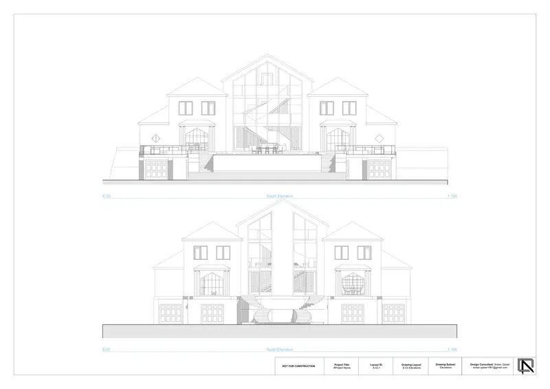
Texas beach house — elevations
Sheet A-0.2.1 — elevations from a permit set
A typical set runs to 24 sheets across 8 series: General, Site, Plans, Elevations, Sections, Enlarged / interior, Details, Schedules.
Every sheet, by series
- General
- G-001 Cover sheet, sheet index & project dataG-002 Code analysis & life-safety plan
- Site
- AS-101 Architectural site plan
- Plans
- AD-101 Existing conditions & demolition planA-101 Floor plansA-102 Floor plans — upper levelsA-111 Reflected ceiling plansA-121 Roof planQ-101 Food-service equipment plan & schedule
- Elevations
- A-201 Exterior elevationsA-202 Exterior elevations (continued)
- Sections
- A-301 Building sectionsA-311 Wall sections
- Enlarged / interior
- A-401 Enlarged plans — kitchens, baths & restroomsA-411 Enlarged unit plansA-421 Interior elevations — kitchens & millworkA-422 Interior elevations — bathrooms & joinery
- Details
- A-501 Envelope detailsA-502 Foundation & slab-edge detailsA-503 Stair, guard & handrail detailsA-504 Millwork & casework detailsA-505 Accessibility details
- Schedules
- A-601 Door & window schedulesA-602 Room finish schedule
In a proposal
How to specify LOD in a proposal
- Set LOD per element or system, not one number for the whole model — walls and openings at LOD 300, say, with MEP at LOD 200 until the engineers' design lands.
- Name the specification and its edition: “BIMForum LOD Specification 2025”.
- Tie each LOD to what the model is for and when — the permit set, trade coordination, fabrication.
- Say who models what: the design team usually to LOD 350, the trades for LOD 400 shop models.
- For existing buildings, state the accuracy you need (the USIBD Level of Accuracy specification is the usual reference) and who verifies it on site.
- Agree whether the drawings or the model govern if the two ever differ.
Our scope
What we deliver
LOD 100–350 is standard, LOD 400 is available by request, and LOD 500 isn't offered.
LOD 350 coordination is part of every BIM model; fabrication-level LOD 400 modelling is quoted separately when a project genuinely needs it. As-built drawings and models are produced from the records you supply — they aren't field-verified, so they are not LOD 500.
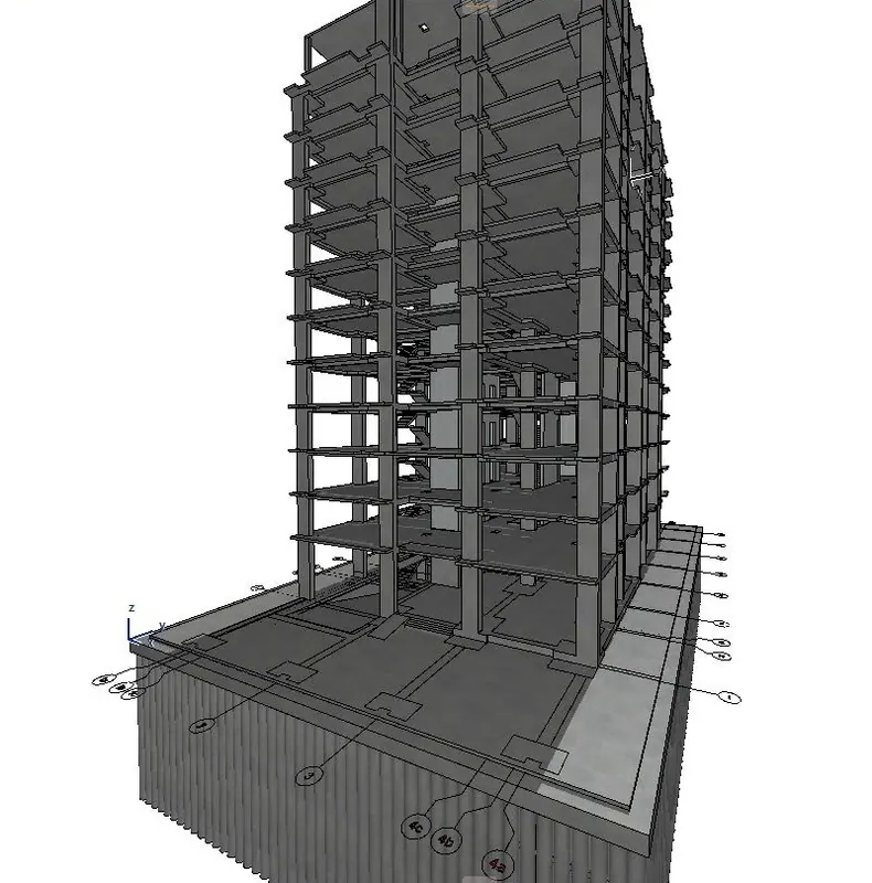
Structural model
Coordinated to LOD 350 — the tower's structural frame
Reference
Standards, glossary and sources
LOD is not a project phase — and how it maps to ISO 7817-1
LOD describes how far a single model element is developed — not how far along the project is. A schematic-design model can already hold LOD 300 elements where decisions have been made, and a construction set can still carry LOD 200 placeholders for items a trade will design later.
The specification is explicit that the levels aren't defined by design phases, though a phase can be described in LOD terms. That's why a good proposal sets LOD element by element — and why the scope estimator here asks where your project is, and leaves LOD to be agreed per element.
LOD and level of information (ISO 7817-1)
LOD is the North American scale for how developed an element is. ISO 7817-1, used widely in the UK and Europe, describes the level of information need instead: for each purpose and milestone, the geometry a deliverable needs — its detail, dimensionality, location, appearance and parametric behaviour — plus the data and documents that go with it.
The two map onto each other well; each level lists the geometry aspects it typically carries.
Glossary — 7 terms
- BIM
- Building Information Modeling — a model of the building whose elements carry data as well as geometry.
- LOD
- Level of Development — how far a model element's geometry and information have been developed and can be relied on.
- LOI / LOIN
- Level of Information / Level of Information Need (ISO 7817-1) — what information a deliverable must carry for a given purpose.
- NCS
- U.S. National CAD Standard — layers, sheet numbering and drawing conventions.
- UDS
- Uniform Drawing System — the part of the NCS that organises sheets by discipline and type (e.g. A-101).
- RFI
- Request for Information — a contractor's formal question about the drawings during construction.
- CA
- Construction Administration — the architect's work during construction: RFIs, submittals, site questions and revisions.
Sources — 5
- BIMForum — Level of Development (LOD) Specification 2025, Part IThe reference for every level above. Licensed CC BY-NC-ND 4.0; the definitions here are paraphrased — see the specification for its exact wording.
- BIMForum — Official release of the 2025 LOD Specification
- ISO 7817-1 — Building information modelling: Level of information needThe geometry aspects in the tables (detail, dimensionality, location, appearance, parametric behaviour).
- USIBD — Level of Accuracy (LOA) SpecificationHow to state the accuracy of field-verified (LOD 500) work.
- U.S. National CAD Standard (NCS) and Uniform Drawing System (UDS)Sheet numbering and drawing-set organisation.